There are varying opinions and thoughts on braking systems for the older Willys era Jeep platforms. Some in the industry say they don’t go fast enough for the factory drum style brakes to be inadequate. Others will argue that four corner disc brakes are the only way to go. We wanted to do a disc brake conversion of our own so our viewers could see the installation process.
Personally, I am a big fan of disc over drum brakes for many reasons. I like the ability to pull a wheel and quickly get a visual on my braking components versus pulling a drum to inspect them. Anyone who’s had to pull drums off of these old Willys knows how much trouble they can be. For those considering a disc brake conversion, it may boil down to cost. To some that much of an investment could quite possibly be as much as they have invested in the vehicle itself.
We just happen to be doing a full restoration of an old, Willy’s era Jeep and decided to take the plunge and do the disc brake conversion. Since there will be several upgrades on this build, we can justify the cost associated to this upgrade. Additionally, it will be a great addition to our “How-To” section to show others what the kit consists of. The back axle is the quickest and easiest so we decided to start there. Since it would be relatively painless and would also allow us to make quick progress, it was a no brainer.
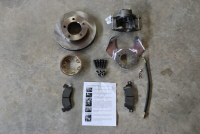
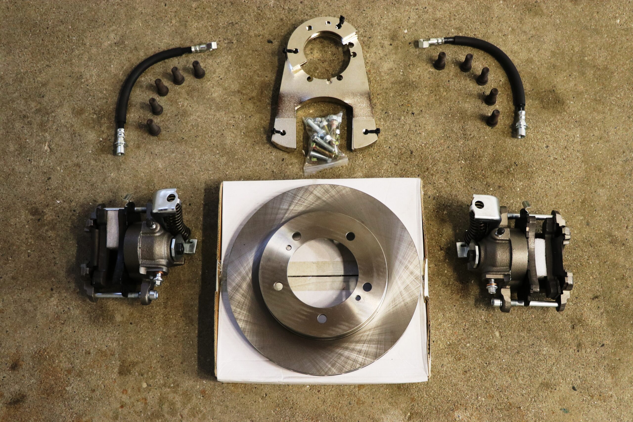
We completely went through the rear housing with new bearings and seals sourced from our friends over at Kaiser-Willys. Next we set the ring and pinion up and the wheel end-play so that once those tasks were completed, we had a fully prepped axle ready for the installation. We also sourced our conversion kit from the folks over at Kaiser-Willys. The kit came with everything we needed including all brackets, bolts, calipers, rotors and new wheel studs. The kit is pretty straight forward and packaged as a whole. Each caliper bracket is even marked to differentiate left from right to help make it fool proof.
Before beginning with the installation you’ll want to ensure the end-play is set on your axle shaft. If you are going to be doing this conversion on an assembled, running vehicle as we presume most will be. The wheels, tires, drum brakes and backing plate will need to be removed in order to start the process. The kit comes with new wheel studs so we pressed them in thinking we would get that out of the way first and foremost but…
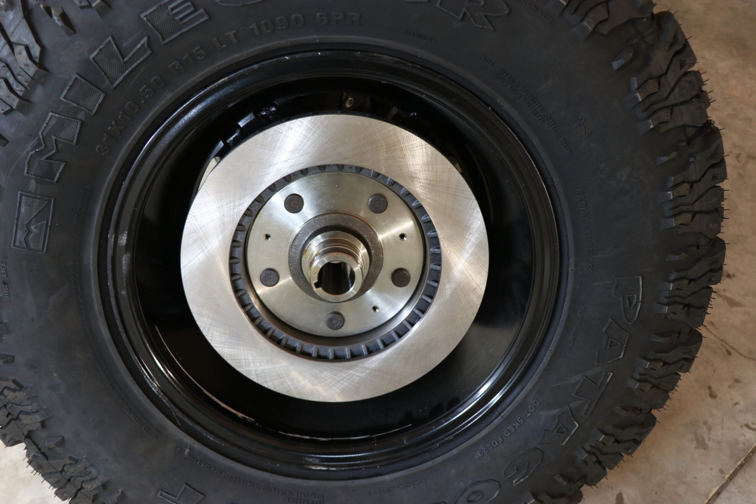
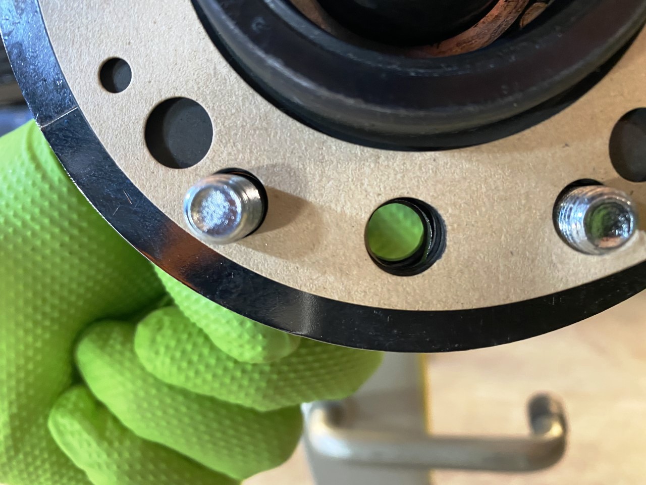
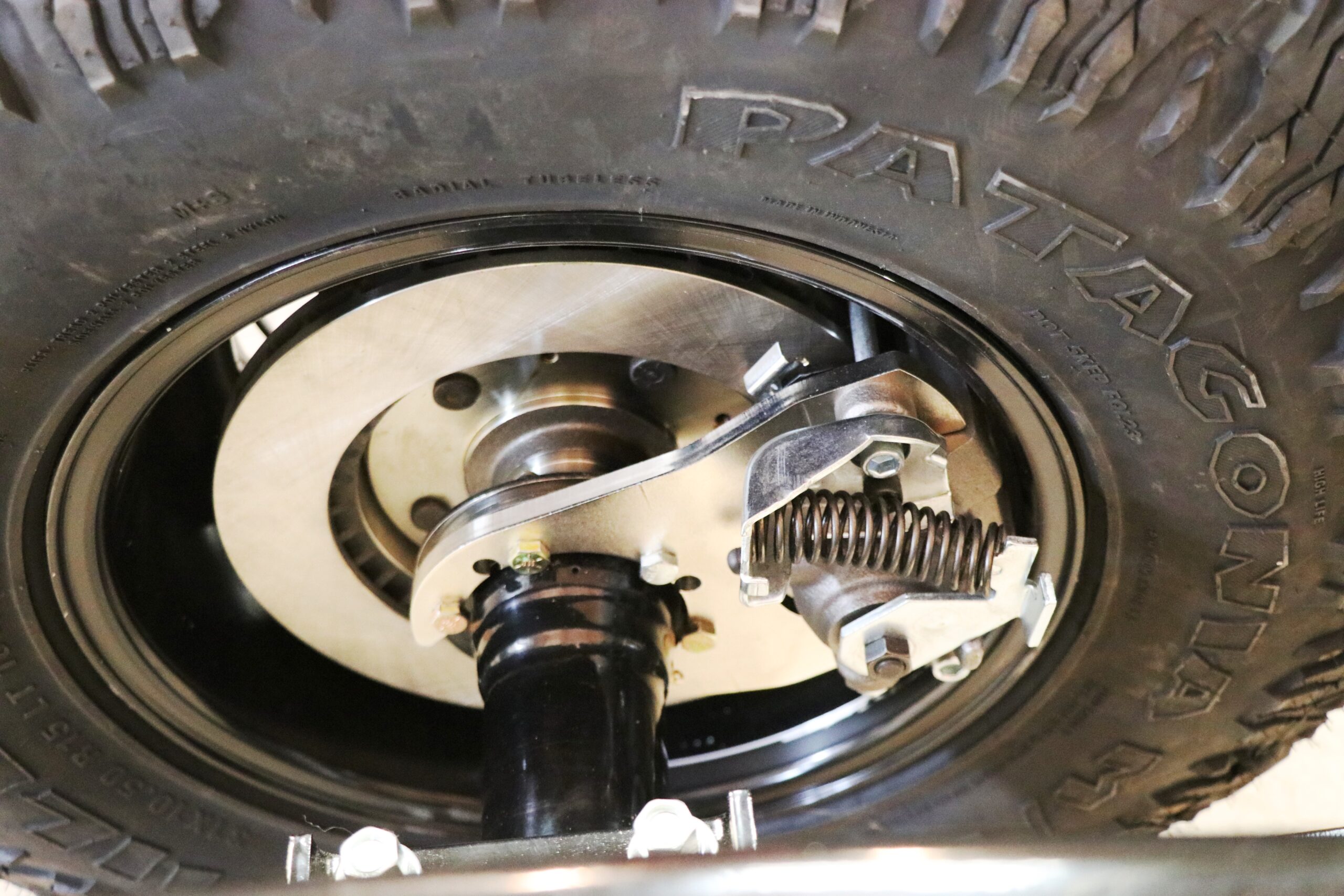
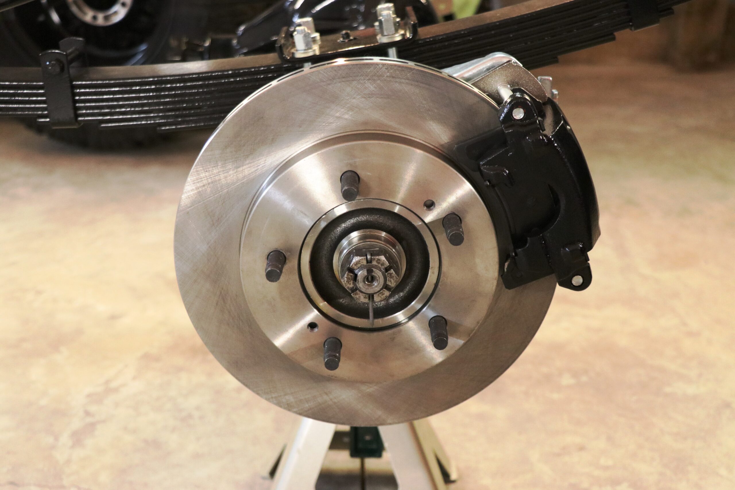
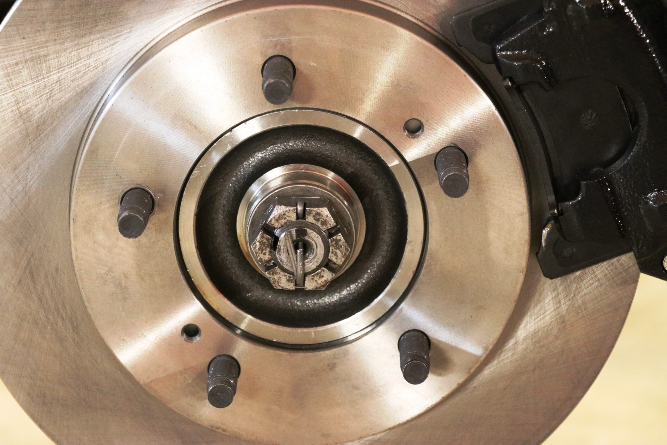
After looking at our wheels it didn’t appear that the studs included with the kit would be long enough. We mocked up the hub, rotor and wheel to see if they would all bolt together but unfortunately they didn’t. Notice pictures 5, 6 and 7 in the first gallery. (We’ll have more details on that to follow later in the article).
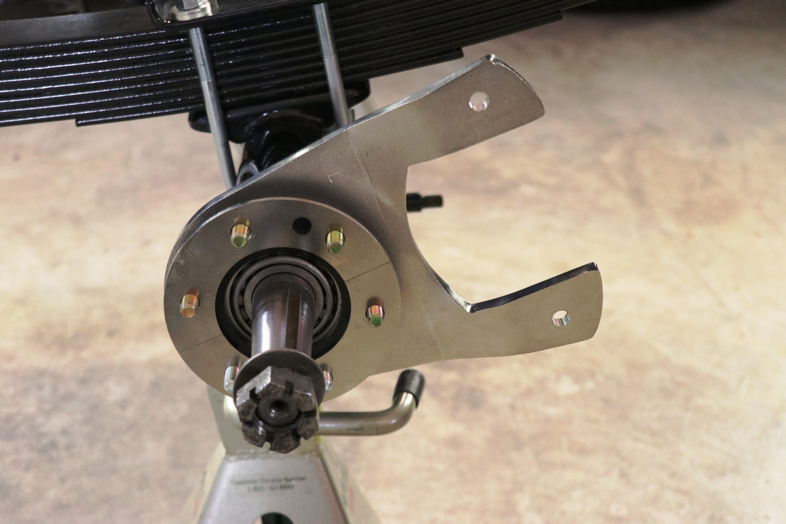
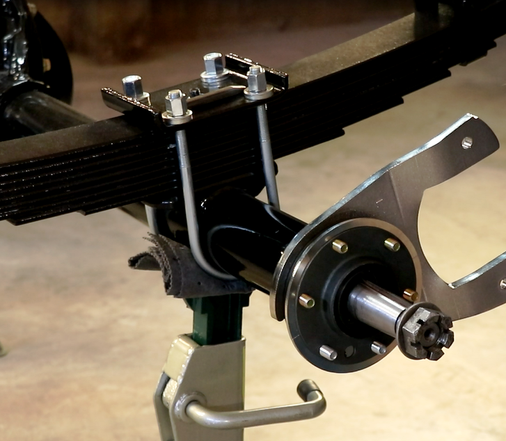
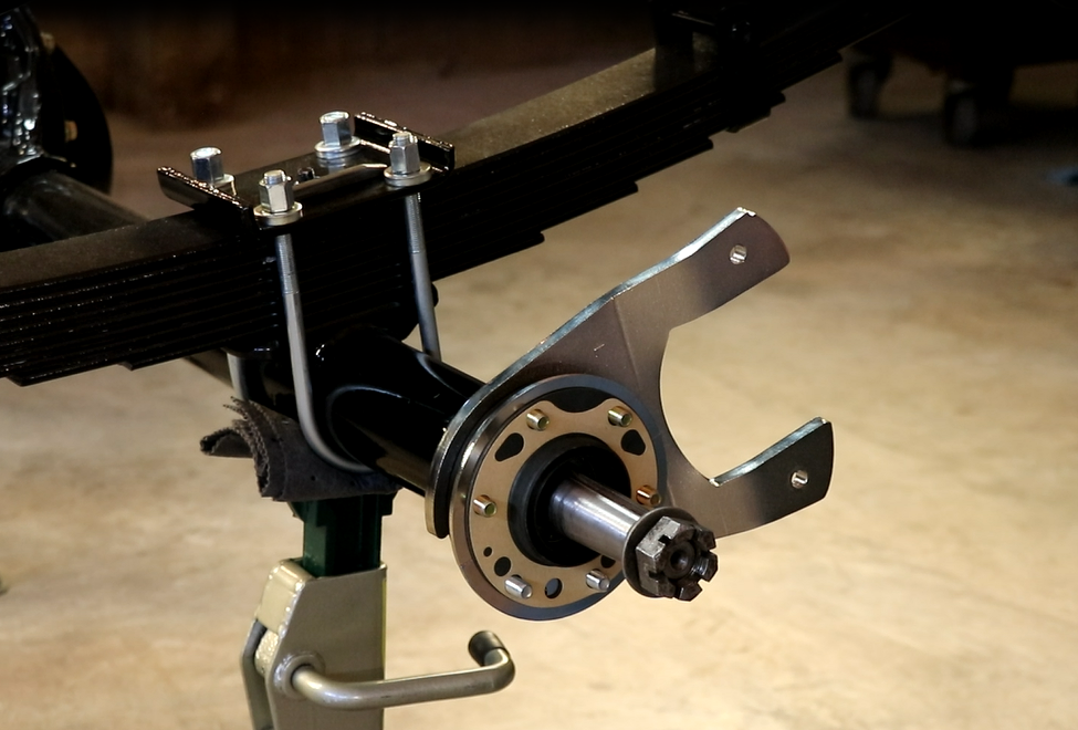
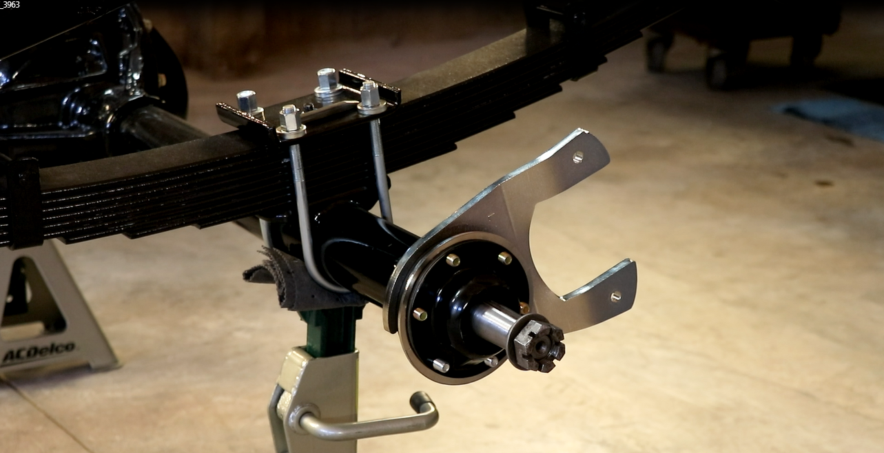
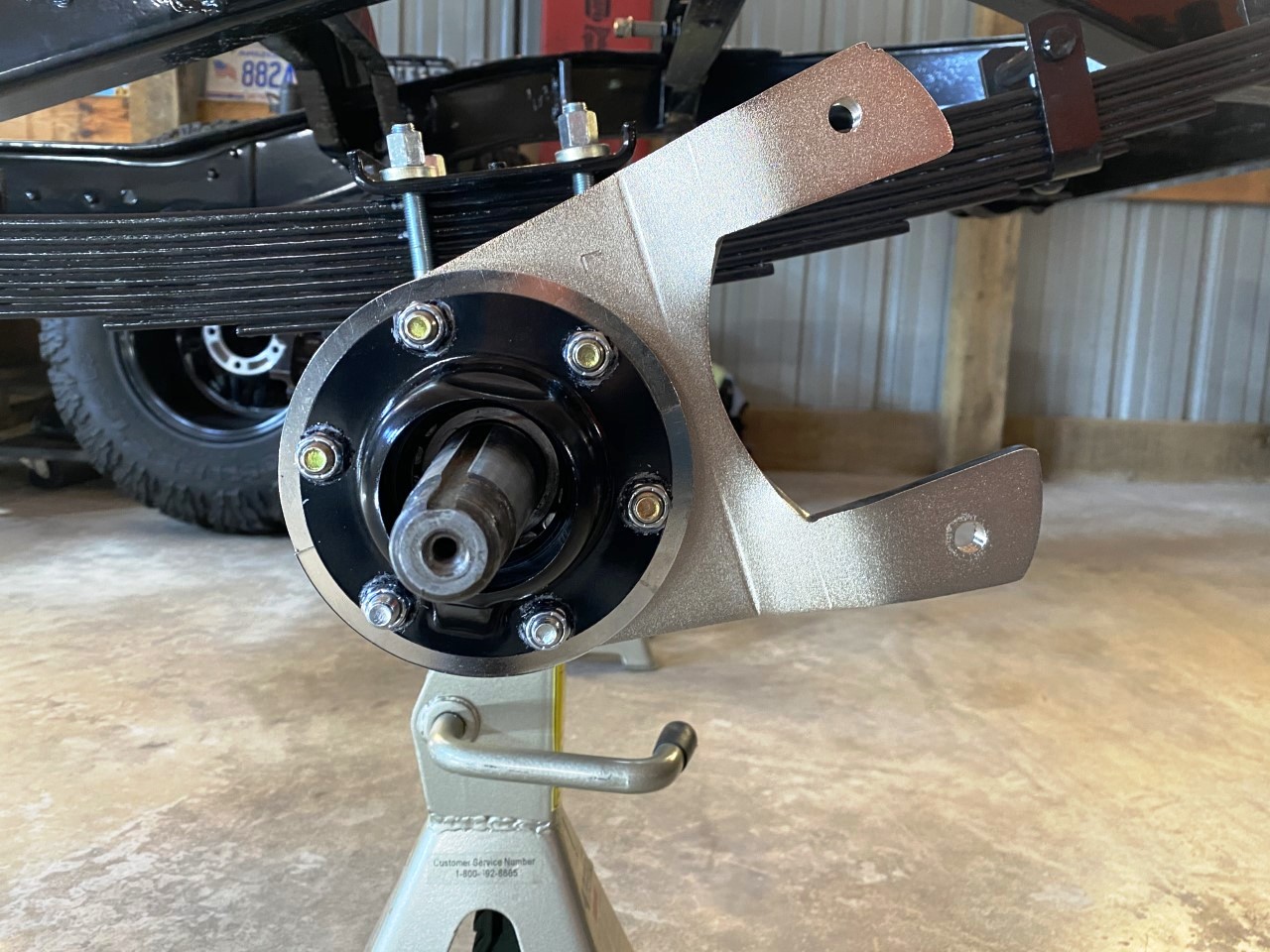
The first components to be mounted are the caliper brackets; these must be installed on the inboard side of the axle flange. Each bracket is held in place with six bolts (all included in the kit) with one bolt being shorter than the other five. The five longer bolts will go through the caliper bracket itself. The shorter bolt will go in the last available opening; all bolts will be installed from the inboard side out. Both brackets have a bend in the design; the bend will need to be facing outwards or away from the frame for proper placement or direction. When correctly installed the driver’s side caliper bracket should roughly be in the 2 o’clock position, and the passenger’s side in the 10 o’clock position.


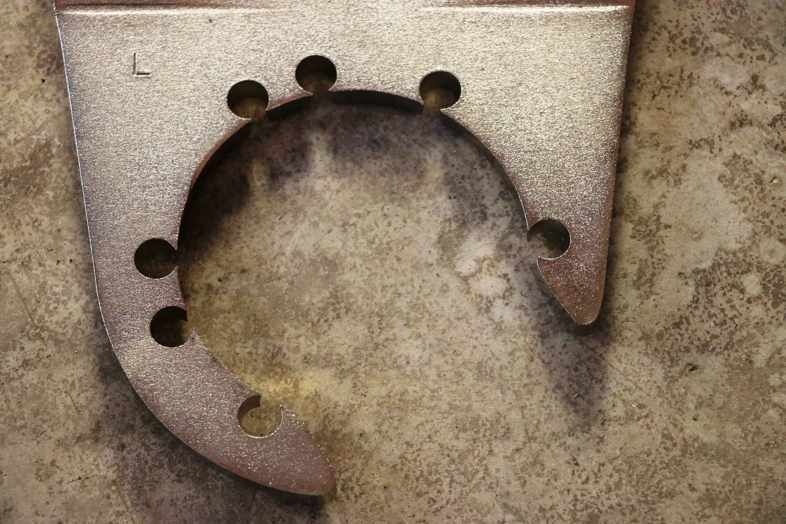
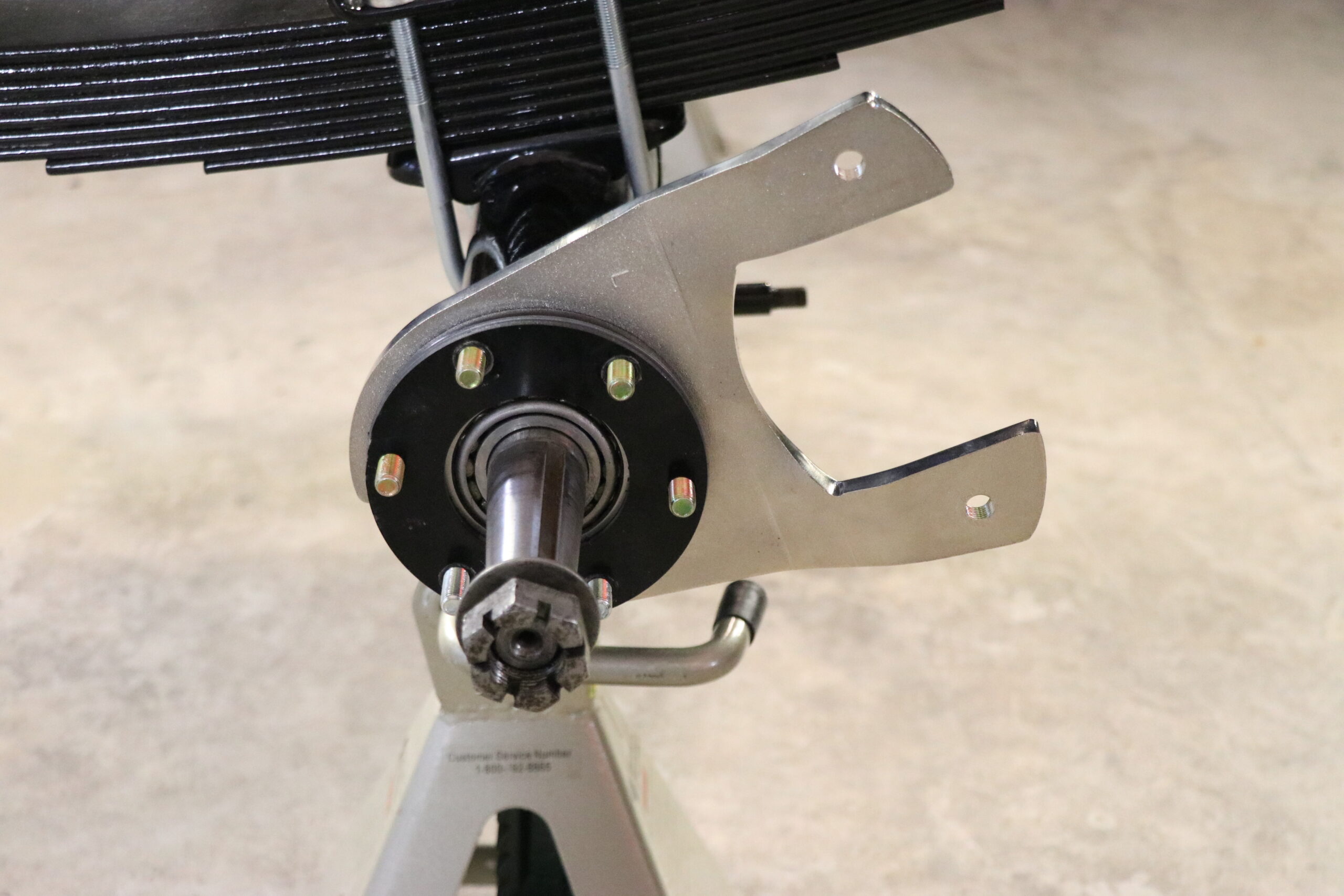
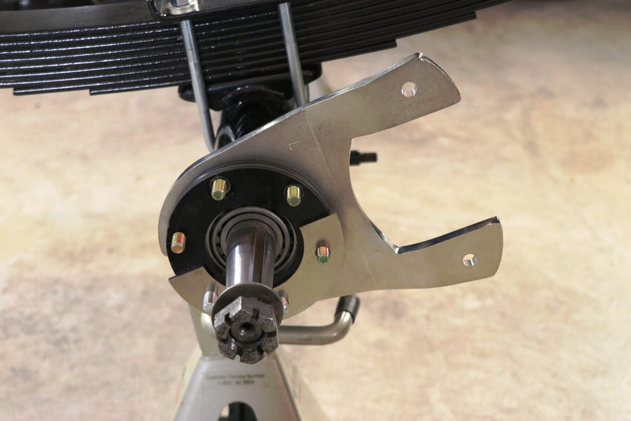
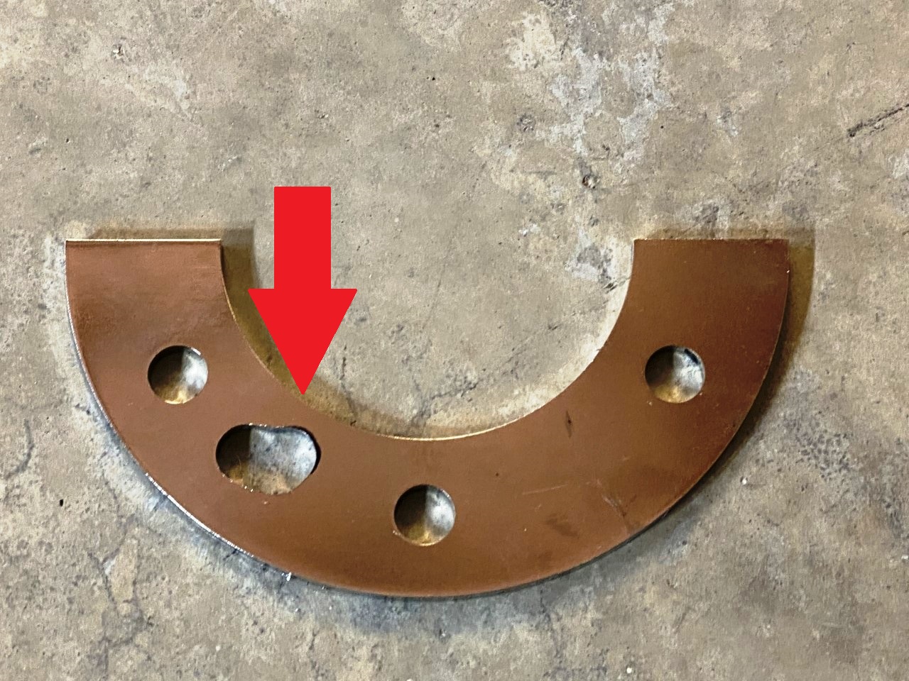
With the caliper mount in place, the axle flange, shims and bearing retainer plate temporarily held in place with the provided bolts, the next components to be installed with be the half moon shaped spacers. These spacers take the place of the original drum backing plate. You’ll notice there is one additional hole that doesn’t line up with the studs. This is a drain hole and is designed to be positioned at the bottom. The extra hole is intended to line up with the grease retainer cap drain channel. This allows any drainage to pass through the gaskets, spacer plate and axle flange. Make sure those holes are all aligned and open so it will function properly.
The hole in our spacers didn’t line up in any of the configurations we tried. We eventually marked each lower spacer and ground out the hole to be fully open and functional as intended.


Once the spacer plates are in place the next step is to install a gasket. Then the grease seal or retainer and then one more gasket followed by the grease retainer cap. With all of those components in place you will then be able to bolt the assembly together.

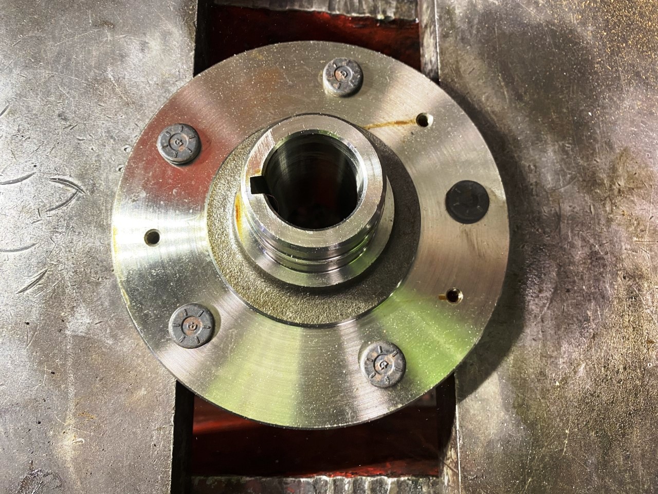
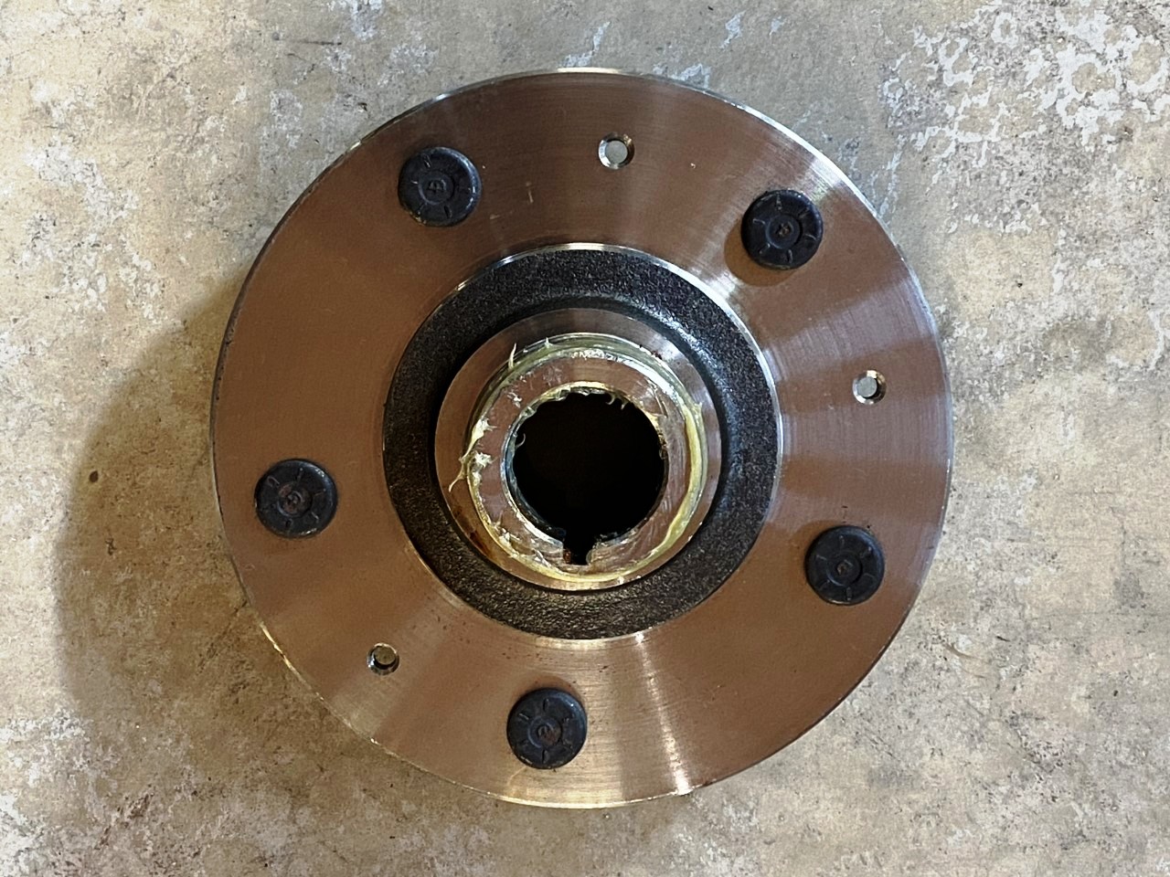
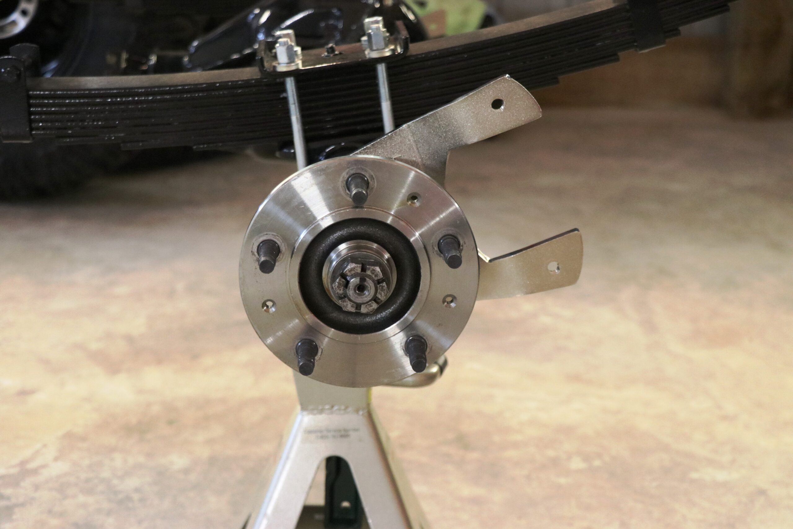
The installation of the hub will be next. Be sure to put some grease on the hub to help ensure you don’t damage the grease seal. Install the hub with the axle key aligned so you can put the key in place when the hub is on (it is recommended to replace the axle key with a new one at this time). If you put the axle key in after the hub is on you are less likely to damage or crack the hub if it slides or slips inward during the installation.
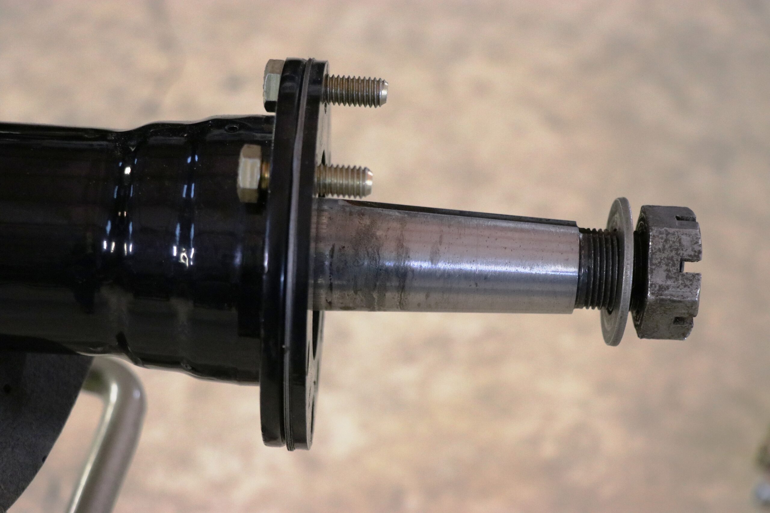
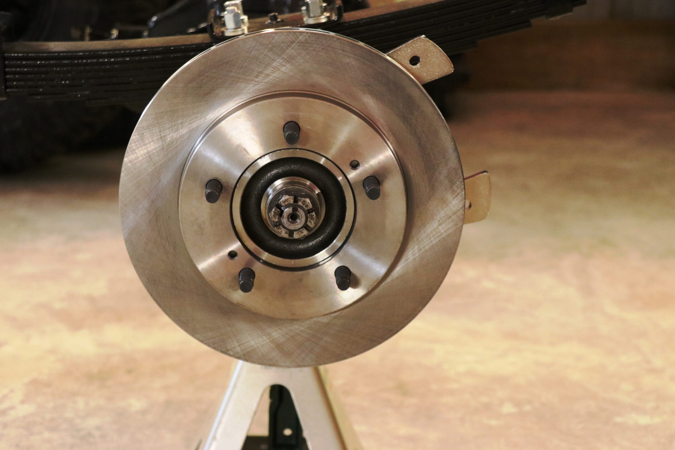
With the hub and axle key installed use the washer and castle nut to tighten the hub into place. The brake rotor can be put on and will be held onto the hub when you tighten down the wheel. Once the rotor is resting on the wheel studs and hub, the brake caliper can be installed onto the caliper bracket that was mounted in step one.

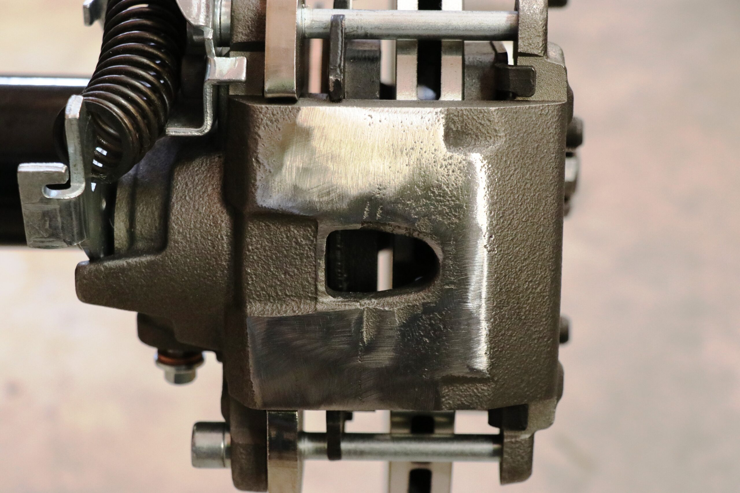
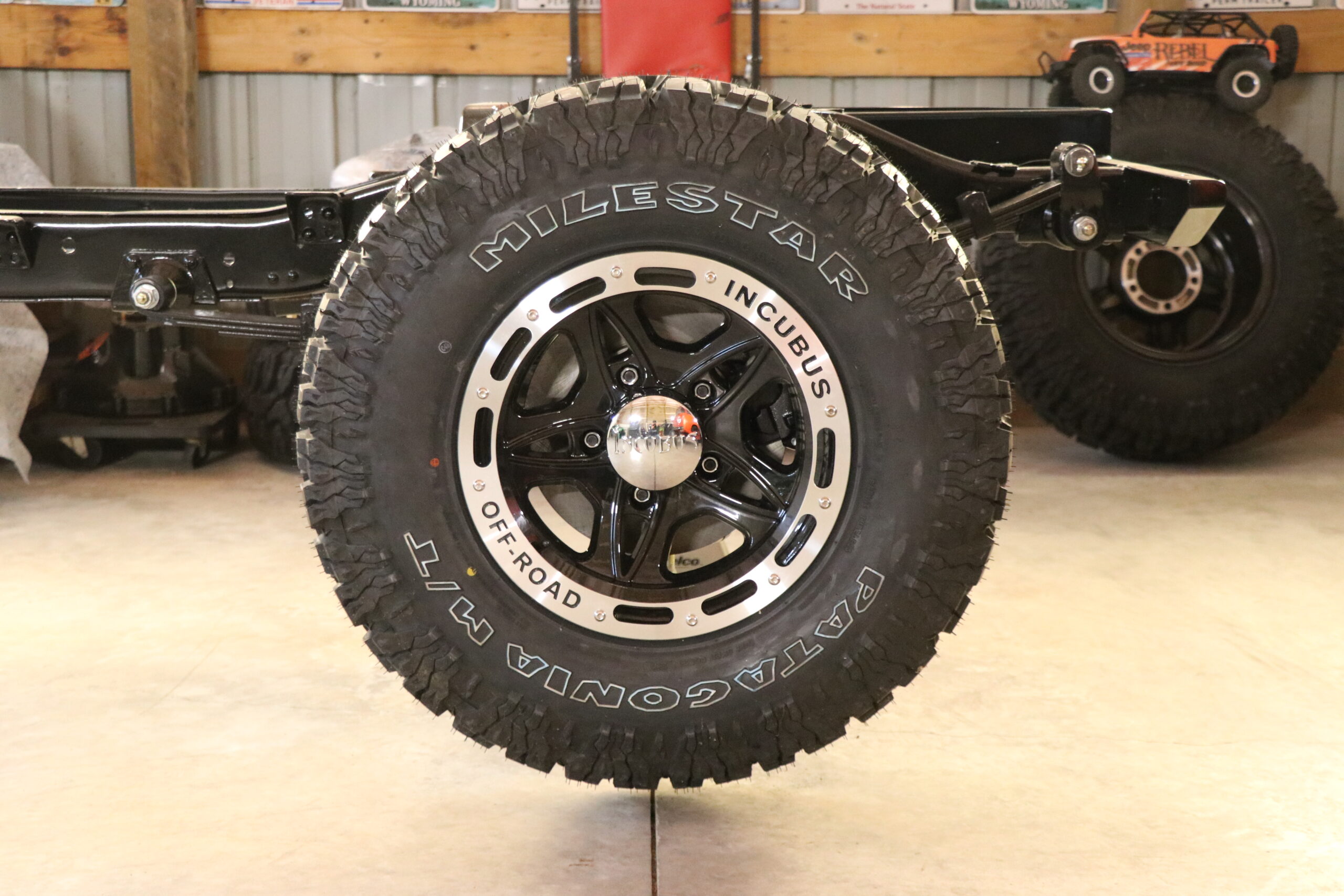
Knowing the caliper clearance would be tight we went ahead and mounted the wheel to see if there was enough clearance for it to spin freely without interference from the caliper. The wheel fit but when rotated by hand, we could hear the caliper scraping on the inside of the wheel. Upon closer inspection it was evident that there was an issue but it appeared minimal enough that the clearance issue could be fixed by grinding off a very small amount of the caliper itself. Once the desired spacing was achieved, the caliper was painted and ready for the final installation.


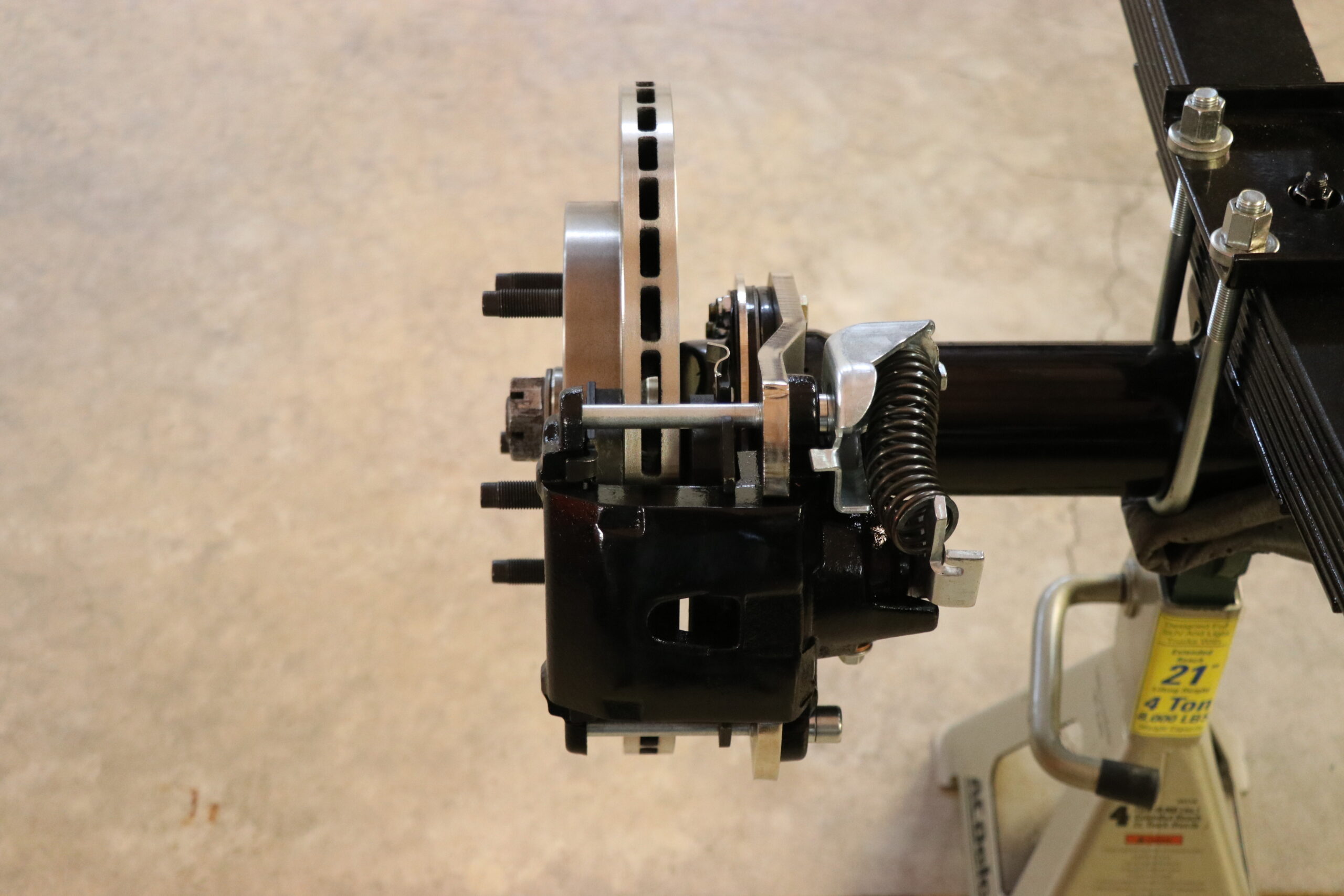
With everything securely mounted in place and properly tightened, the last task was to put the cotter pin in place, mount the wheels and wrap things up so we could get the back half of this project on the ground.
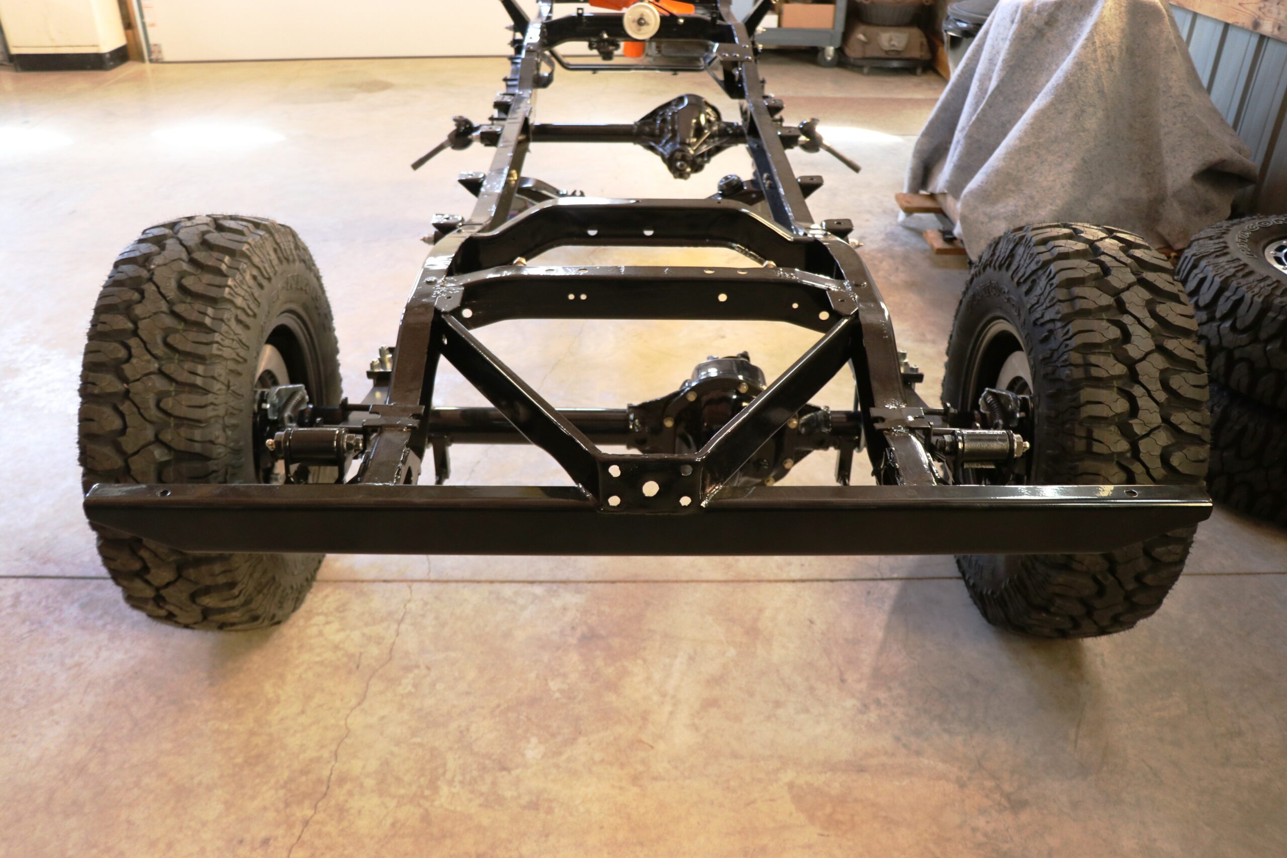
Hopefully this will help guide anyone with the desire to do a rear disc brake conversion through the process. It really wasn’t a difficult process, more so time consuming than anything.
For those who prefer video instructions versus text, here is a link to the YouTube video of the installation.
Additional Notes:
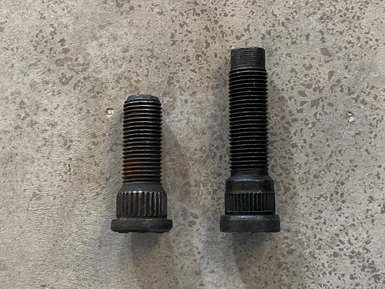
Wheel Studs: As mentioned earlier, we run into a couple of issues on this installation. The fact that the kit includes instructions specifically stating the kit will not work with factory wheels one would assume that aftermarket wheels would be utilized in order to make the kit work and longer wheel studs would have been included to begin with.
With a quick trip to our local NAPA Auto Parts we were able to pick up some longer wheel studs. The part number we utilized for ½ – 20 wheel studs was 641-4260. The downside is that it added almost another $20 per wheel.
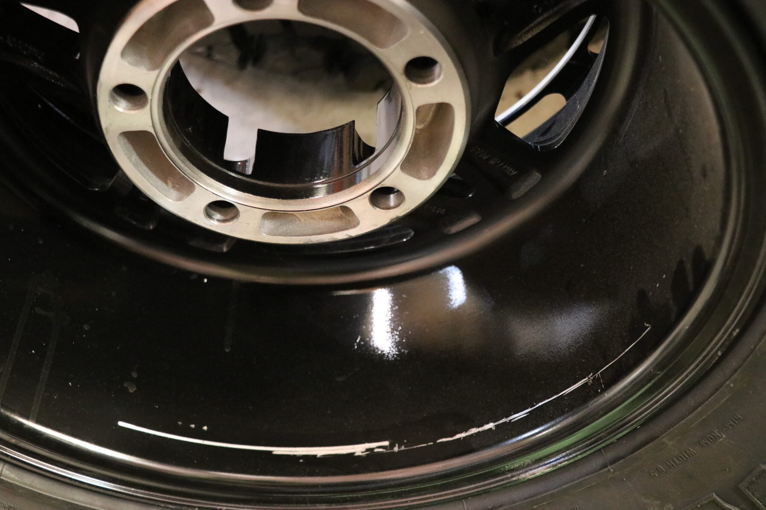
Brake Caliper: As we also noted in the write up, there were clearance issues with the caliper hitting the wheel itself. This caused the edge on the caliper to cut gouges into inside surface of the wheel. We ground off a small amount of the caliper which gave plenty of clearance for the wheel to rotate freely.
Torque Specs: Always refer to any owners or repair manuals for proper torque specifications on any components requiring a specific torque rating.